(Louis Meulstee’s web site)
 Home
Return
ASR 1
ASR 2
ASR 3
ASR 4


Gibson Girl part 3. Air-Sea Rescue: Post war VHF and UHF systems
 Top of page
Post War Air-Sea Rescue
The on long wave and short wave based Gibson Girl transmitters remained in general use for Air-Sea rescue after World War 2, not only by the military but also aboard civil aircraft. Other systems, however, were devised generally based on VHF as were the British 'Walter' and German NS4. This concluding part will not go in detail with every aspect of later systems, but giving a minor account on some typical examples of man carried Air-Sea rescue beacons. Two frequencies were eventually allotted to (Air-Sea) rescue operations: VHF 121.5MHz and UHF 243MHz. Some of the radios, notably the AN/URC-4, were capable of operating on either
frequency. The general tendency was, however, the use of a
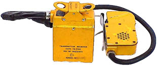
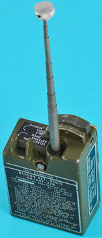
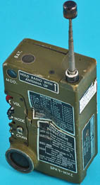
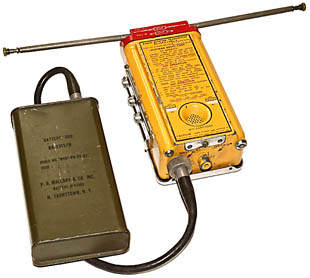
Transmitter/Receiver RT-159A/URC-4 was a VHF/UHF Air-Sea rescue set made in the USA. It operated on either VHF 121.5MHz or UHF 243MHz. VHF or UHF operation was performed by a band switch located on the side of the set and the setting of the length of the horizontal part of the telescopic antenna. The transmitter used voice or tone transmission and could thus be received by any standard aircraft VHF or UHF receiver. The circuit comprised a three stage crystal controlled transmitter, and a superregenerative receiver with a single RF stage. See the circuit diagram here. The loudspeaker was also used as microphone in transmit position. Five pencil valves and one 7-pin miniature valve were used in the set.
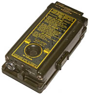
Shown top-right is the 'yellow' version of this set; also known is a 'green' olive drab version (right). The battery was connected to the URC-4 by a short connector.
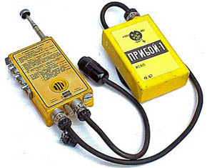
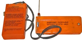
Russian air-sea rescue set type R 855-U (left) operated on VHF 121.5 MHz and comprised the complete transmitter-receiver and battery unit. The antenna was a vertical telescopic rod of about 60cm in length. The set used a combination of valves and transistors. Its use was noted in the 1960s. Apart from normal speech transmission and reception, pulsed tone could be transmitted.
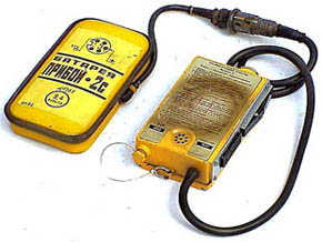
The later issued (about mid-1970s) Soviet type R 855-UM Variation 'C' (right) operating on 121.5MHz was functionally very similar in use and smaller in shape. Transistors were used throughout.
A version operating on 121.7 MHz has been spotted.
The Russian RM-4 operated on VHF and UHF. Further details have not yet been found.
Examples of later issued USA SAR sets were the URT-33 (above) and URC-64 (below)
single band. Most of the radios described in this part operated on 121.5MHz. Not all the Air-Sea rescue transmitters were one-way beacons, some models had limited receive facilities and could be used to make a speech call if a rescue aircraft or ship was within (limited) range. This facility reduced the working life of the battery. Note that most of the VHF and UHF air-sea rescue transmitters and beacons (also known as SARBE) were also used to assist in locating he survivors of land crashes; being small and inconspicuous they were indispensable during rescue operations on enemy territory.

AN/CRC-7 (left) was an USA rescue transmitter-receiver operating on VHF 140.580MHz. It had speech facilities and tone transmission. The RF output was about 50mW. The set was superseded by the AN/URC-4.
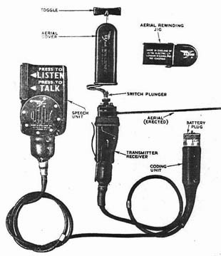
SARAH beacon less battery (above). When not used, the steel tape aerial was winded and stowed in the aerial cover.
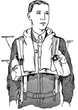
How a SARAH beacon was carried in the life vest.
(Top right)
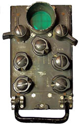
Combined transmitter-receiver and indicator as installed in rescue aircraft and launches. (Right)
SARAH
In the early 1950s the British SARAH (Search And Rescue And Homing) equipment was introduced. The system comprised a man-carried automatic distress beacon, and search equipment which was normally installed in an aircraft or a rescue launch.
The distress beacon SRI 23006 was a lightweight miniature set operating on UHF. It comprised a speech unit, transmitter-receiver unit, coding unit and combined LT/HT battery. The first three units were permanently interconnected. Attached to the transmitter/receiver unit was a leaf spring aerial which folded up to very small dimensions.
The SARAH beacon had three modes of operation: In the normal beacon condition pulses on a frequency of 243 MHz were automatically transmitted. See the circuit diagram. The pulses were transmitted in a rate of 210 pairs per second, the spacing between the pulses in each pair was determined by a coding unit and was a distinguishing feature between the beacons. (Note that the normal beacon operation had some elements in common with the war-time 'Walter' beacon).
The peak power in this mode was 15 watts and the battery life about 20 hours continuous operation. The SARAH beacon was normally powered by a combined sealed LT/HT battery; later versions had a transistorised power supply consisting of a LT battery attached to a transistor inverter. Two way speech communication with the rescue craft was possible using the Talk and Listen buttons, the range on speech mode was considerably lower with a much higher power consumption.
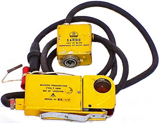
Valves were still used in the SARBE T-10050 transmitter (right). This set comprised three units: the battery (not shown), modulator and actual transmitter with (folded) steel tape antenna. Operation was on VHF 121.5MHz.
SARBE TR-9783 (right) was a transmitter-receiver operating on VHF 121.5 MHz. No further technical details are known whether valves or a hybrid of valves and transistors were used. Noted is the a olive drab coloured version, aligned on different VHF air frequencies, used by the Army as an interim solution for communication by isolated patrol parties to supply aircraft.
SARBE BE 361/243/D (above) was a beacon transmitter operating on 243 MHz. Its size was very small and it was fully transistorised. It is believed that other versions of this pulsed tone beacon operated on 121.5 MHz.
SARBE
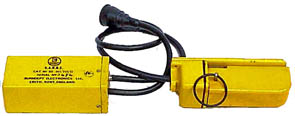
In the UK a variety of different SARBE Search And Rescue Beacons have been developed, notably those manufactured by Burndept Electronics Ltd.
